Monday, April 25, 2005

Timeline Update -- Phase 1

Phase 1 is now complete!

This phase was to determine whether the project was possible. It explored different graphics components based on openGL. It also focused on current trends in research related to haptics and visual representation. The scope and major hurdles for the project were determined. The project will proceed.

Issues Encountered:

Issues encountered have either been resolved or a work around exists. One issue was the discovery of the limit of the haptic device. The force feedback is only in 3 dimensions. A fully functional system must incorporate at least 5 degrees of freedom feedback. To overcome this issue, all drilling be done perpendicular to the drilling plane.

Another issue was moving the tool center point (TCP) of the haptic device. As stated in other posts, the TCP must be at the drilling endpoint. Using the HDAPI the TCP can be moved and have forces generated based on the new position. The remaining issue is that the HLAPI cannot be used without modifying its source code. Using the HDAPI requires custom collision detection and force rendering.

Accomplishments:

An openGL graphic environment was created. An ASCII STL file can be loaded. Force feedback can be generated using the STL file. A voxel shell can be loaded into the environment and the haptic device can simulate removing pieces. Camera angles can be moved.

Known Issues:

Haptic to viewing transformation/mapping
Must implement custom force/collision detection -- HLAPI cannot be used
How to attach drilling device to haptic device.
Drawing 100,000 Voxels is upper limit of machine

Skills and Knowledge Acquired:

programming with openGL
What voxels are and their costs and benefits
how to incorporate API's into existing code
what callbacks are and how they interact with a scheduler
Interact with developers using Sensable Developers Forum
Week Update April 22, 2005

Resolved Issues:

StlViewer was modified to allow the haptic cursor to interact with the voxel shell. The problem was matching the coordinate systems. The voxel shell was drawn incorrectly. When the original voxelization pyramid was used, the cursor interacted with voxel object.

Remaining Issues:

Must migrate to HDAPI
Determining the correct scale of the voxel shell around the STL object.

Questions:

How to resolve system lag, mainly openGL optimizations can Oct trees be used?
Should STL object be voxelized for 3 layer collision detection?
Collision Detection -- Voxel based, Cylinder to Plane
How to attach drilling device to haptic device?

Answered Questions:

Workspace to graphics mapping. See Post for Workspace Mapping
Would there be a benefit from using VTK. See Post VTK

Friday, April 22, 2005

Force Rendering and Collision Detection -- Plan

The HDAPI allows the HD_CURRENT_FORCE variable to be set. This provides the developer with control of custom force rendering. The SlidingContact example creates a force field around two sphere objects. Collision detection is used to update the force on the cursor object and then sent to the haptic device.

Our prototype system will take advantage of custom force control and collision detection. The collision detection will be divided into either 2 or 3 stages.
  1. The first stage is a collision between the cursor and the voxel shell.
  2. The second stage would involve voxelizing the STL object. This stage is meant to reduce the number of collision checks by creating a rough outer shell of the STL object. This stage is only needed if the collision detection between the STL file and the cursor proves to be too expensive.
  3. The last stage is to do collision detection between the cursor (tooltip) and the STL object. This is an expensive operation because STL files are normally not optimized. A sample STL file rendered had 1600 facets. Various collision detection algorithms will be explored for this issue.

Voxels are used in this program to represent 3D shapes as well as provide quick collision detection. A collision between the cursor and the voxel object can be detected by checking the coordinates of the cursor. If it lies within the voxel coordinates a collision has occured. The voxels that are within the cursor coordinates can be checked whether they are part of the body or are free.

An important assumption is that the STL object will lie within the voxel object. Collision detection between the cursor and the STL object only needs to be done when the cursor lies within the voxel space. The STL object is static and a voxel representation can be created but only to reduce the number of collision checks. The voxel object will have a changing shape and the goal is to represent the STL object as voxels.

Thursday, April 21, 2005

Haptic Device to Graphic Mapping

For the past few weeks, I have been struggling to convert the haptic work coordinates to the graphic coordinates. I have been modifying code given in the haptic examples. The simpleHapticScene example provides code to generate the cursor on the screen.

The problem was having the coordinate system of the haptic cursor interact with the voxel shell. The cursor could be drawn to the screen, but when the cursor should have crossed into the voxel shell nothing happened.

Project stlViewer took code from a voxelization project. This took a geometric pyramid and created a voxel shape from this. Dr. Horsch modified this to distinguish the outer shell and the inner body, where the outer shell voxels are drawn. Our project will only require a voxel shell without the need for the voxelization step. I modified the code to create a cube that was 127^3 with only the outer shell drawn.

The next step was allowing the keyboard to move the cursor in the virtual environment and remove voxels when a collision occured. I modified the code provided by Dr. Horsch to activate the invisible voxels surrounding the one that was removed. When a collision occured with a voxel, its neighbors that were not drawn before had there type changed to be on the border.

The haptic toolkit provides a way to get the final transformation. There are two levels, the HL and the HD. The HL provides a proxy transformation that is the calculated with an extra translation. The HD provides the exact transformation; that is, it provides the machine values.

Today I found out that I was multiplying by the wrong transformations. The code provided by simplehapticscene to draw the haptic cursor uses a mapping technique to draw the cursor. I have struggled to get this to work, so instead I took the HD_CURRENT_TRANSFORM and generated the cursor at that position.

Tuesday, April 19, 2005

Callbacks and the Scheduler -- From a HDAPI viewpoint

The Scheduler is the thread controlling the haptic device. This is the main interface and runs at 1000Hz. Queries such as position or state must be accessed by calls to the scheduler. The scheduler allows get and set operations to many hardware variables, i.e. position or force.

The HD requires creating CallBacks to be run on the scheduler. Some Events are predefined, but the custom functions can also be passed to the scheduler. The CallBacks can be sent to run every frame, scheduled by the programmer, or triggered by predefined events.

  • Asynchronous -- "return immediately after being scheduled" represent haptic effects
  • Synchronous -- "only return after they are completed, ...application thread waits for a synchronous call before continuing." Use to get snapshot of state/variables

[1] OpenHaptics Toolkit - Programmer's Guide 5-5 37/118

CallBacks have two return types.

  • HD_CALLBACK_CONTINUE -- The CallBack will be rescheduled to run on next tick
  • HD_CALLBACK_DONE -- Will not be rescheduled

Examples

hdScheduleSynchronous(DeviceStateCallback, &state, HD_MIN_SCHEDULER_PRIORITY);
hdScheduleAsynchronous(AForceSettingCallback, (void*)0, HD_DEFAULT_SCHEDULER_PRIORITY
);

HLAPI -- Forces and Collision Detection

The section called HDAPI vs. HLAPI mentioned that the HL used openGl to render haptic feedback. The HL commands to capture the shapes are wrapped around existing openGL code.

Depth Buffer -- The HL reads the openGl depth buffer to calculate the geometry and render forces. "The depth buffer is used for hidden surface removal." [1]

Depth buffer shapes are less accurate than feedback buffer shapes although in nearly all
applications, the difference in accuracy is undetectable. [2]

Feedback Buffer -- "Capture geometric primitieves" Commands that generate points, lines and polygons. [1]

If you are rendering lines and points to be used as constraints, you must use a feedbackbuffer shape since depth buffer shapes cannot capture points and lines.[2]


[1] The OpenHaptics™ Toolkit: A Library for Adding 3D Touch™ Navigation and Haptics to Graphics Applications
Brandon Itkowitz* Josh Handley† Weihang Zhu

[2] OHTK Programmer's Guide 7-12 page 62/118

Saturday, April 16, 2005


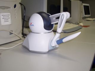
SensAble Omni Phantom

Visualization ToolKit (VTK) -- To integrate or not to integrate

"The Visualization ToolKit (VTK) is an open source, freely available software system for 3D computer graphics, image processing, and visualization..."
VTK Home Page http://www.vtk.org/ 16 April 2005

The initial phase of the project was to determine whether to design a system bottom up or to modify an existing engine. The VTK provides many features, automatic lighting, an STL file reader, and a marching cubes implementation. Using the VTK marching cubes implementation would decrease design time but is not crutial to the system. I have implemented an ASCII STL reader.

The control of openGL is hidden from the programmer and this is the main downside of using this system. Integrating the controls of the haptic device would be required and it is unknown if it is possible or . Another issue is the workspace to graphics mapping. Since the openGL calls are hidden, it is unclear whether the model transformation matrix is accessible.

At this point in time, the risks of switching to the VTK outweigh the benefits.

HDAPI vs. HLAPI

The HDAPI provides low-level access to the haptic device, enables haptics programmers to render forces directly, offers control over configuring the runtime behavior of the drivers, and provides convenient utility features and debugging aids.

The HLAPI provides high-level haptic rendering and is designed to be familiar to OpenGL® API programmers. It allows significant reuse of existing OpenGL code and greatly simplifies synchronization of the haptics and graphics threads. The PHANTOM Device Drivers support all shipping PHANTOM devices.

3D TOUCH™ SDK OPENHAPTICS™ TOOLKIT PROGRAMMER’S GUIDE
2004 SensAble Technologies

Voxels -- What to Know

Definition:
  • The term voxel is short for volume pixel. Pixels represent only two dimensions. Voxels allow objects to be represented in 3 dimensions. Voxels are used to represent volume data, such as CAT scans and MRIs.

In Use:

  • A 3 dimension array will represent the voxels. The array type will be an unsigned char, where a zero is outside of the object, a one would represent the outer shell of the object, a two would represent the undrawn inside of the object.
  • The memory size will increase with resolution (ex. 128 cells in each x, y and z coordinates as an unsigned char)
  • Voxelization is the process of converting a set of geometric shapes into a voxel representation. A problem is finding a ratio of memory size to resolution. One technique for voxelization is presented by
    E. Karabassi, G. Papaioannou, T. Theoharis, "A Fast Depth Buffer Based Voxelization Algorithm,
    Journal of Graphics Tools", ACM, 4(4), pp.5-10, 1999.

Project Specific Assumptions:

  • The real world material will be represented by a voxel shell. The material will be cuboid, not required to be cubic. The original object does not require voxelization, because of its shape. The STL object could be voxelized to enhance collision detection.
  • if tooltip is within voxel coordinates
  • check for collision with voxel outer shell
  • check for collision with STL voxel shell
  • use other collision detection to check for contact with STL
    object
  • Voxels are used because of quick collision detection. The position of where an object collides with the voxel shell can be checked easily. X, Y and Z coordinates with the offsets figured in will determine which cells need to be checked. If any cells have a value of one, being part of the outer shell, then a collision has occured.

Week update April 15, 2005

Current Issues:
  • Mapping the Cursor/haptic device Workspace to Screen coordinates.
  • Including tooltip transformation: Current Projects rely on Haptic Library to Render forces. The translation for the tooltip requires the projects moving away from the Haptic Library(HL) API and using the Haptic Device(HD) API. The HL is a high level library that automates most processes, including capturing and rendering forces. The HD requires callbacks to be written to simulate forces and provide collision detection.
  • Collision Detection techniques
  • Migrate working systems to HD
  • Calculate and Generate custom forces


Current State of System: Projects

stlViewer

  • The haptic tooltip can be drawn on the screen
  • Loads STL object
  • Loads a voxel shell, the shell is updated when contact occurs with cursor
  • Allows cursor control with keyboard or haptic interface
  • With keyboard control, voxel shell can be deformed

Issues:

  • Relies on HL to capture shapes from OpenGL calls
  • Must migrate to HD
  • Does not include tooltip transformation
  • haptic cursor does not interact with voxel shell correctly

Various Toolkit Examples:

  • Slidingcontact has been modified to demonstrate the possibility of adding the translation using HD.
  • cubeTest loads a STL file and allows haptic feedback. The forces are rendered by the openGL viewing matrix. If the viewing matrix shows the virtual model at an angle, then the forces will correspond to the viewing shape not the actual shape. This project uses HL and has a mapping of the workspace to visual display.

Questions:

  • How to map workspace
  • Collision Detection -- Voxel based, Cylinder to Plane
  • How to resolve system lag, mainly openGL optimizations can Oct trees be used
  • Should STL object be voxelized for 3 layer collision detection
  • Would there be a benefit from using VTK

Counters